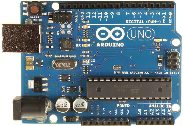
What is Arduino Uno?
Arduino UNO is based on the Atmega328P microcontroller which is developed by Arduino.cc which is an open-source microcontroller board.
It is a widely used board than other Arduino Boards.
The board provides sets of digital and analog I / O pins (input/output), which can be interfaced in various extension boards (shields) and other circuits.
The board has 14 digital pins that can be used as input/output. From that 14 digital pins, 6 pins can be used as PWM outputs. D3, D5, D6, D9, D10, and D11 are the PWM pins in Arduino UNO.
PWM (Pulse Width Modulation) is a technique to get analog results from digital means. PWM mainly used in Arduino for controlling Servo Motors, LEDs, Speed Controlling, etc.
The board has 6 analog pins. It has a 16 MHz quartz crystal oscillator which provides a clock signal to microcontroller Atmega 328.
The board has a USB port that is used to program the board and also for giving power.
It has a power jack, an ICSP header, reset button, and LEDs.
This board contains everything needed to support the microcontroller, to get started simply connect it to a computer with a USB cable or power it with battery or an AC-to-DC adapter.
Must Read:
Technical Specification of Arduino Uno
| Microcontroller | ATmega328P |
| Operating Voltage | 5V |
| Input Voltage (recommended) | 7-12V |
| Input Voltage (limit) | 6-20V |
| Digital I/O Pins | 14 (of which 6 provide PWM output) |
| Analog Input Pins | 6 |
| DC Current per I/O Pin | 20 mA |
| DC Current for 3.3V Pin | 50 mA |
| Flash Memory | 32 KB (ATmega328P) of which 0.5 KB used by bootloader |
| SRAM | 2 KB (ATmega328P) |
| EEPROM | 1 KB (ATmega328P) |
| Clock Speed | 16 MHz |
| LED_BUILTIN | 13 |
| Length | 68.6 mm |
| Width | 53.4 mm |
| Weight | 25 g |
Arduino Uno Pinout
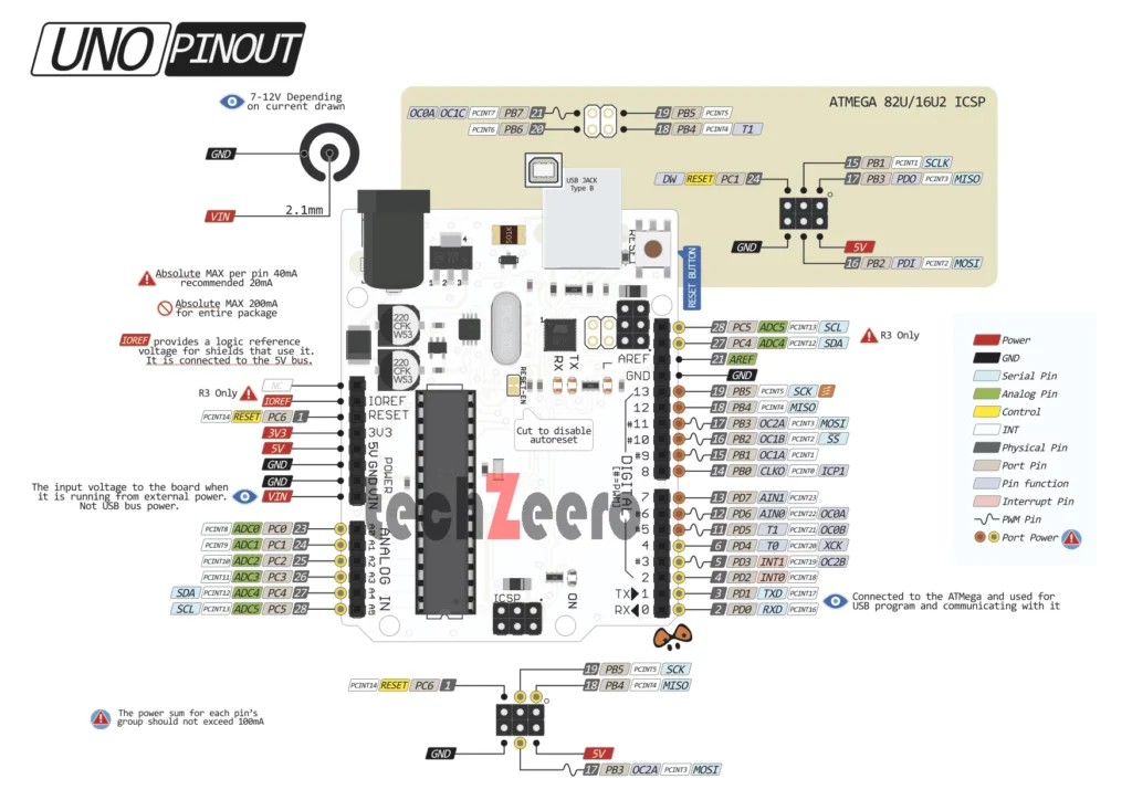
The Arduino UNO board can be powered by USB connection or Power Jack with an external power supply. We have to use an AC to DC Adapter of 2.1 mm centre-positive plug into the board’s power jack. The board can work on an external supply of 6 to 20 volts. If using more than 12V, the voltage regulator may be overheated and damage the board
- Vin:- The input voltage to the Arduino board when it’s using an external power source you can supply voltage through this pin. If the supplying voltage via USB connection or the power jack, you can access it through this pin.
- 5V: – This pin gives the output of 5V. You can use this pin to give a 5V supply to the sensor.
- 3V3:- This pin gives the output of 3.3V. The maximum current drawn is 50 mA.
- GND:- These pins use as Ground Pins.
- IOREF:- On the Arduino board, this pin provides voltage references, with which the microcontroller operates. A properly configured gradient can read the IOREF pin voltage and can work with 5V or 3.3V to select a suitable power source on the output or enable the voltage translator on the output.
Note:- Do not supply voltage via the 5V or 3.3V pins, it bypasses the regulator and can damage the board. We don’t advise it.