Introduction to LED and Potentiometer
Are you ready to dive into the exciting world of controlling LEDs with a potentiometer? Get ready to illuminate your projects with creativity and versatility as we explore how these two components work together seamlessly. Whether you’re a seasoned electronics enthusiast or a curious beginner, this blog post will guide you through the fascinating process of LED control using a potentiometer. Let’s light up the way!
In old televisions and stereo, you might have seen a knob rounded button for changing the channel and adjusting volume.
Mainly you had seen light strings in which this type of function is used. We control the delay time of LED blinking, we replace the value of the delay time from the potentiometer reading variable.
Arduino read Analog value by analogRead Function. The voltage is adjusted by the potentiometer.
Components Needed
- Potentiometer
- Arduino Uno
- LED
- Resistor
Potentiometer Pinout
When working with a potentiometer to control an LED, understanding the pinout is essential. The three pins on a potentiometer are typically labeled as the input pin, output pin, and ground pin.
The input pin connects to the power source or Arduino board’s analog input, while the output pin links to the circuit you want to control—such as an LED. The ground pin serves as the reference point for electrical current flow.
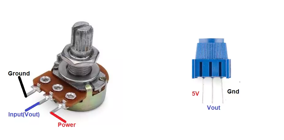
By correctly identifying each pin’s function, you can seamlessly integrate the potentiometer into your LED circuit design.
Remember that different types of potentiometers may have variations in their pin configurations, so always refer to the datasheet for precise details.
Mastering the potentiometer’s pinout opens up a world of possibilities for customizing and fine-tuning your LED projects with precision and ease.
Pin Connections
| Potentiometer and LED Pins | Arduino Pins |
|---|---|
| 5v or Vin | 5V |
| GND | GND |
| Vout | A0 |
| LED anode | D5 |
| LED cathode | GND |
Use of Resistor with LED is mandatory otherwise LED will burst.
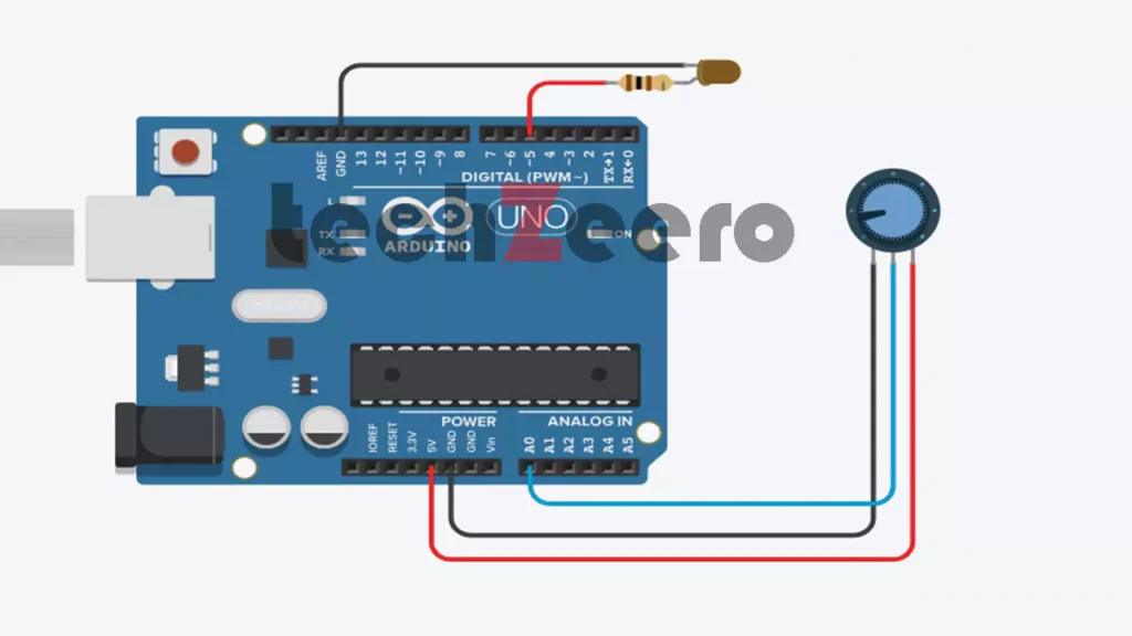
Circuit Diagram of LED with Potentiometer
When it comes to creating a circuit diagram for controlling an LED with a potentiometer, simplicity is key. The setup typically involves connecting the positive leg of the LED to one end of the potentiometer and then linking the other end of the potentiometer to ground.
It’s essential to ensure that all connections are secure and correctly placed on your breadboard or PCB. Double-checking your wiring before powering up the circuit can help avoid any potential issues down the line.
Connect the potentiometer and led with Arduino according to the below circuit diagram.
Code for Controlling LED with Potentiometer
Now, let’s dive into the exciting world of coding to control an LED with a potentiometer. By using Arduino IDE, we can easily write a simple script that reads the analog input from the potentiometer and adjusts the blinking of the LED accordingly.
Define the pins for the LED and potentiometer in your code. Then, read the analog value from the potentiometer using `analogRead()`. Next, use this value in delay() function for controlling the blinking of the LED.
Upload the below code and adjust the potentiometer knob to see the change in the blinking rate of led.
Output
Once the LED circuit with potentiometer is set up and the code is uploaded, it’s time to see the magic in action. As you turn the potentiometer knob, the blinking of the LED will change accordingly. It’s fascinating to witness how a simple twist can alter the blinking speed of the LED.
If the voltage on pin decreases on increasing the rotation of the potentiometer, you can reverse the connections of the VCC and GND pins.
Tips for Troubleshooting and Adjusting the Circuit
Having trouble with your LED and potentiometer circuit? Don’t fret, troubleshooting can be a breeze with a few simple tips.
Double-check all your connections to ensure everything is properly wired. Loose connections can lead to unexpected behavior in the circuit. Next, make sure your components are of good quality and functioning correctly; sometimes faulty parts can cause issues.
If you’re still facing problems, try adjusting the resistance of the potentiometer slowly while observing the LED’s blinking. This will help you find the sweet spot where the LED shines at your desired intensity.
Additionally, consider using a multimeter to measure voltage across different points in the circuit – this can pinpoint any irregularities that may be causing issues.
Remember, patience is key when troubleshooting electronics. Take your time, follow these tips diligently, and you’ll have your circuit working smoothly in no time!
Creative Applications of LED and Potentiometer Control
Looking to take your LED projects to the next level? Get creative with the control of LEDs using a potentiometer!
- Imagine designing interactive art installations where users can adjust the brightness or color of LEDs by simply turning a knob. This dynamic feature adds an element of user engagement and customization.
- Potentiometers offer endless possibilities for creating mood lighting in bedrooms, living rooms, or even outdoor spaces. By integrating them with LEDs, you can easily set the ambiance based on your preferences.
- For tech enthusiasts, combining potentiometers with LEDs opens doors to crafting unique gadgets like adjustable flashlights, DIY dimmer switches for lamps, or even personalized illuminated signs.
- The marriage of LED and potentiometer control unleashes a world of innovation waiting to be explored. Let your imagination run wild as you experiment with different ways to harness their potential in your projects!