Introduction to RGB LEDs and Arduino
Have you ever wanted to add a splash of color to your Arduino projects? RGB LEDs are the perfect solution! These versatile components allow you to create stunning light displays with just a few simple lines of code. In this blog post, we will guide you through how to use an RGB LED with Arduino, from setting up the circuit to programming eye-catching color patterns. Get ready to bring your creations to life with vibrant hues and dynamic effects!
An RGB LED consists of three colors in combinations, but we can make more color by using these colors i.e red, green and blue.
Here some more tutorials for you:
- Ultrasonic Sensor with Arduino
- DHT11 Temperature and Humidity Sensor With Arduino
- LED Blinking Control by Potentiometer
- Controlling Multiple LEDs With Arduino Uno
- How to use an LCD Display with Arduino
What is RGB LED?
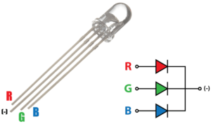
RGB LEDs have red, green and blue elements in a single package. The RGB LED consists of four pins with either anode connected together (known as a common anode) or cathodes connected together (known as a common cathode).
Mainly these types of RGB LEDs are used in lamps, decorative lights and string lights.
In this tutorial, we will use the RGB LED which has a common cathode and different anodes are red, green and blue.
Components Needed
A breadboard comes in handy for prototyping and testing your circuit before finalizing it. Don’t forget about a USB cable to power up your Arduino board during programming and testing phases. With these essential components in hand, you’re ready to dive into creating captivating light displays with your RGB LED and Arduino setup!
- RGB LED
- 3 Resistors (300Ω – 1 KΩ)
- Arduino Uno
- Breadboard
- Jumper Wires
Pin Connections
Carefully place the RGB LED on the breadboard ensuring each pin is properly connected. Remember that each color (red, green, blue) has its designated pin on the LED. Next, connect one leg of the RGB LED to a digital pin on your Arduino using jumper wires.
We use common cathode RGB led. Connect the cathode of the RGB LED which is a longer leg to the Ground (GND) of Arduino and the other three legs to pin 3, 5 and 6 of Arduino along with a 220 ohms resistor with each leg. The resistor will prevent the current flow and LED bursting. Refer to the below circuit diagram.
By following these steps diligently and experimenting with different combinations in your code, you’ll soon be amazed at what stunning colors and effects you can achieve with your RGB LED and Arduino setup. Happy tinkering!
Once you’ve securely connected the RGB LED to your Arduino board, it’s time to write some code! Open your preferred coding software and start programming commands to control each color channel individually or create dynamic color-changing effects.
Circuit Diagram

Code for RGB LED Arduino
Now that you have your circuit set up, it’s time to dive into the exciting world of programming the Arduino for RGB LED control. This step is where the magic happens as you get to unleash your creativity by manipulating colors and effects with just a few lines of code.
Make sure you have the Arduino IDE installed on your computer. This software will be your gateway to writing and uploading code to your Arduino board. Once you have it all set up, open a new sketch and start by defining which pins on the Arduino are connected to each color (red, green, blue) of the RGB LED.
Next, you can begin experimenting with different functions such as analogWrite() to control the intensity of each color channel or mixing colors by combining different brightness levels. By adjusting these values in your code, you can create an array of vibrant hues and dynamic lighting effects that will surely impress anyone who sees them.
Don’t be afraid to play around with loops, conditional statements, and other programming concepts. The beauty of working with RGB LEDs and Arduino is that there are endless possibilities for customization and personalization. So roll up your sleeves, get creative with your coding skills, and watch in awe as your RGB LED comes to life with stunning displays of light!
Output
Once you have set up your RGB LED circuit and programmed the Arduino board, it’s time to see the output in action. When you power up the Arduino, you will witness the magic of colors illuminating from your RGB LED. The RGB LED will start displaying different hues based on your code.
Watching the colors blend and transition smoothly is a mesmerizing experience. You can control each color channel independently or mix them together to create unique shades. Experiment with changing brightness levels and patterns to add more flair to your project.
In the above example, we have code the Arduino to blink the RGB LED. The RGB led shows only three colors red, green and blue while blinking.
Now We want to adjust the color of RGB led to show more colors. We use the RGB_color function to explore more colors.
Code for Adjusting Color of RGB LED
Once you’ve mastered controlling the RGB LED with Arduino, the fun really begins when you start creating different colors and effects. By adjusting the intensity of each color channel – red, green, and blue – you can mix them to produce a wide range of hues. Want a calming blue? Increase the blue intensity while lowering red and green.
For a vibrant purple, blend red and blue together at higher levels. Experimenting with patterns like fading in and out or transitioning smoothly between colors adds depth to your projects. You could even synchronize the LED with music for an interactive light show!
By incorporating variables into your code, you can dynamically change colors based on sensor inputs or create custom sequences for special events. The possibilities are endless when it comes to customizing your RGB LED projects!
In the below code, RGB_color(255, 0, 0) is color code function, if there is a particular color that you want to try and create, find yourself a web color chart by typing web color chart into your favorite search engine.
Another Code for Adjusting the color of RGB LED
Advanced projects and applications using RGB LEDs and Arduino
Ready to take your RGB LED projects to the next level? With Arduino’s versatility and the dynamic range of RGB LEDs, the possibilities are endless.
One advanced application is creating a color-changing mood lamp that shifts hues gradually for ambiance. By programming intricate patterns and transitions, you can craft mesmerizing light shows.
For more interactive experiences, consider integrating sensors like motion detectors or sound modules. Imagine a responsive LED installation that changes color in sync with music or movement.
Delve into IoT by connecting your RGB LED setup to the cloud for remote control via Wi-Fi or Bluetooth. You could design custom lighting schemes from anywhere in the world!
Experiment with multiplexing techniques to control multiple RGB LEDs independently, opening up avenues for large-scale displays and immersive installations.
Troubleshooting / Errors
Troubleshooting common issues when working with RGB LEDs and Arduino is a part of the learning process. One common problem you might encounter is incorrect wiring – double-check your connections to ensure everything is properly connected.
- Incorrect LED connection, so make sure that the LED connection is correct.
- Use a resistor to avoid the problem of LED bursting.
- The wire connection may be loose.
